Hyperspectral
Line-Scan Camera Overview
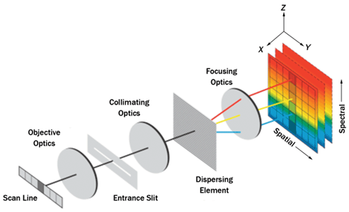
Line-scan, or "pushbroom," cameras capture imagery one line of spatial pixels (one pixel tall, n pixels wide). With hyperspectral line-scanners, each pixel contains discrete spectral information across dozens or hundreds of wavelengths. A complete two-dimensional image is formed by moving the sensor’s swath (field of view) across the scene, sequentially assembling each line into a continuous image or "cube." In UAS applications, this motion is provided by the forward flight of the aircraft, crafting a cube line by line across the flight path.
Unlike traditional frame-based cameras, which capture two spatial dimensions simultaneously, line-scan hyperspectral sensors trade one spatial dimension for extensive spectral resolution. This configuration allows for the precise measurement of reflectance characteristics across a wide range of wavelengths, offering enhanced capability for material identification, vegetation analysis, and other spectrally driven remote-sensing applications.

Data Collection Considerations
Platform Stability
Hyperspectral line-scanners are among the most challenging modalities for UAV data collection because even small instabilities can distort the raw imagery. Since a pushbroom sensor captures only one line of pixels at a time, any changes in the UAV’s attitude (roll, pitch, or yaw) while scanning can warp the resulting image. GRYFN's orthorectification technique can reduce and correct this distortion during post-processing, but minimizing them during flight remains critical.
Aircraft design and stability are therefore critical factors influencing hyperspectral orthorectification quality. Larger UAV platforms with higher inertia, slower-turning propellers, and streamlined airframes tend to provide the most stable imaging conditions. Maintaining a center of gravity aligned between the airframe and payload further enhances balance and stability. Conversely, lightweight UAVs operating near their maximum lift capacity or with less aerodynamic designs are more susceptible to attitude fluctuations, reducing the quality of the orthorectification process.
Illumination, Exposure, and Frame Rate
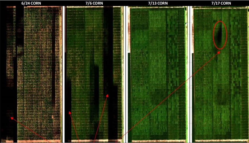
Hyperspectral cameras are very sensitive to lighting conditions and radiometric quality is highly dependent on scene illumination and consistency. To ensure accurate reflectance measurements, illumination in the scene must remain bright and stable throughout data collection. Flights should be conducted within ±2 hours of solar noon under clear sky conditions, when solar radiation and sun angles are optimal. In the winter when sun angles are generally lower, this window should be reduced to as little as ±1 hour from solar noon. See below the impact of a small, short burst of clouds on a hyperspectral data capture. When flights occur outside the solar noon window, long shadows behave much like cloud shading, reducing reflected energy and lowering signal level in the hyperspectral data.

Some hyperspectral experts recommend a solar altitude of no less than 40 degrees. https://www.timeanddate.com/ is one resource that provides accurate solar altitudes, solar noon time, and more. Simply locate your city, click on the Sun & Moon tab, and pan across the Sun Position graph to see solar altitude at a given time. You can also scroll down and open See Full Month's Sun to open a table and graph for any given day of the year to see the solar noon time, and solar altitude degrees.
Three key sensor settings control how data is captured: frame period, exposure time, and gain level. Frame period describes the time to capture each frame (single line of pixels), exposure time specifies how long the sensor integrates light capture within the frame period, and gain mode provides an analog boost to incoming signal. All three settings are set to a fixed value prior to the collect, and are likely to change from one collect to the next.
Frame period has a direct relationship with flight altitude and speed. For a given set of flight parameters, the sensor must capture at a minimum rate (or faster) relative to the altitude and speed of the aircraft to adequately capture all points in the scene.
Exposure time and gain are complimentary parameters. Both parameters impact saturation of the sensor's dynamic range. Gain mode should be set to the lowest level possible that allows an exposure setting to sufficiently saturates the sensor's dynamic range for the spectra of interest. While higher gain modes enable data collection under reduced illumination, they do so at the expense of radiometric quality, producing lower signal-to-noise ratios. Exposure should be set to a value lower than (a faster time) than the frame period value. Exposure time should be adjusted based on available illumination until sufficient saturation is achieved.
Sensor Frame Rate/Frame Period and Flight Speed Relationship
Line-scan cameras collect data at a fixed frame rate, making stable flight speed essential for producing high-quality hyperspectral data cubes. If the UAV moves faster than the camera’s frame rate can accommodate, the image becomes under-sampled, resulting in gaps between spatial frames. Conversely, if the UAV moves slower than the frame rate, the same spatial line may be captured multiple times, creating oversampled data. Oversampling is preferred because it can be corrected during orthorectification and mosaicing, and reduces the potential for gaps between spatial frames as the aircraft's speed or attitude destabilize.
In practice, the frame period of line-scan cameras should be set to match the flight speed, or set such that the frame capture time is faster than traversal over a spatial point. To demonstrate numerically, at a 60m flight altitude and 5m/s flight speed, the Headwall NanoHP with a 12.6mm lens requires a 5.58ms frame period (179 Hz). Thus, a faster frame period (lower number), such as 4.46ms (20% faster), should be used. The level of oversampling required is highly dependent on aircraft stability. Large, more stable aircraft in low winds can achieve sufficient spatial sampling with less oversampling rate used than a light aircraft in strong winds.
Flight Line Overlap
Unlike frame cameras, line-scan cameras require much less overlap between adjacent flight lines, also known as side-overlap or "sidelap." Frame cameras, such as RGB or Thermal, rely on matching features from adjacent overlapping images in order to build a mosaic. In contrast, line-scan cameras use GNSS/INS data to georeference each line, overlaying adjacent flight lines based on precise sensor position. During this process, GRYFN Processing Tool selects pixels near the center of each line to minimize distortion near the edges of the data cube.
Sidelap for line-scan sensors is primarily needed to account for roll instability of the aircraft. A minimum of approximately 30% sidelap is generally sufficient to compensate for these variations. By comparison, frame cameras typically require at least 75% front- and side-overlap to ensure sufficient feature similarity for accurate mosaicking.
Last updated